
Desert Online General Trading LLC
Warehouse # 7, 4th Street, Umm Ramool, Dubai, 30183, Dubai
Desert Online General Trading LLC
Warehouse # 7, 4th Street, Umm Ramool, Dubai, 30183, Dubai


⚡ Generate brilliance, one waveform at a time!
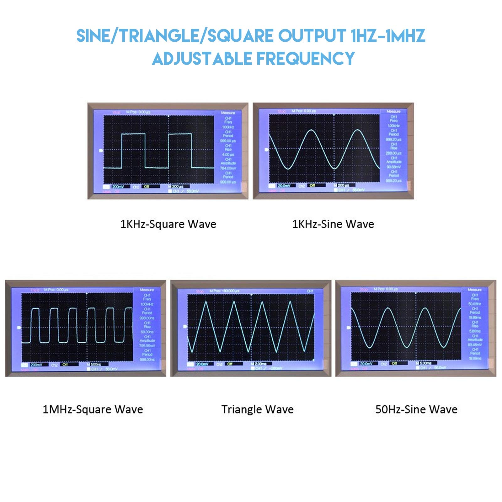
The XR2206 Signal Generator Kit is a precision DIY module offering adjustable sine, triangle, and square wave outputs from 1Hz to 1MHz. Featuring less than 1% distortion and a transparent case for easy assembly, it runs on 9-12V DC and delivers up to 3V amplitude, making it an essential tool for electronics enthusiasts and professionals seeking versatile, high-quality signal generation.


TrustPilot
4天前
1 周前